GPIO Button Input
You can wire a physical button, switch or sensor to a GPIO pin to trigger an FPP event — see GPIO Inputs for how to configure the trigger itself once it's wired. This chapter covers the wiring side: identifying the right pins and choosing between an external or internal pull resistor.
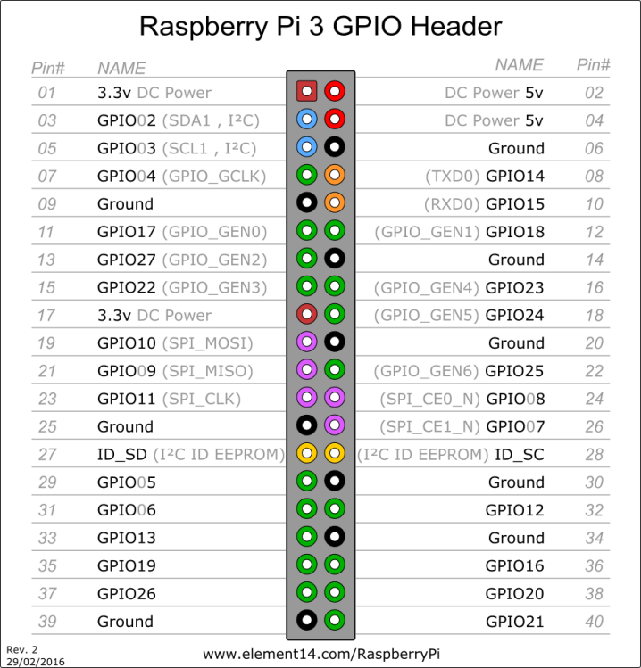
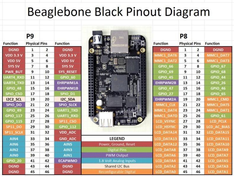
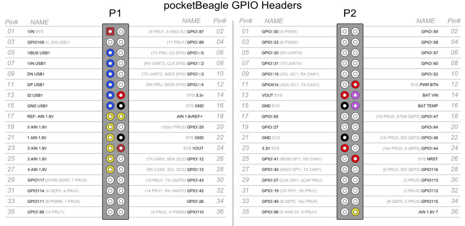
Before making any connections, confirm the GPIO pinout of the SBC you are using, and always wire with the power disconnected.
Pull‑up and pull‑down resistors
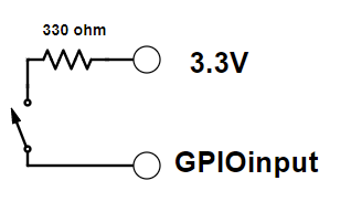
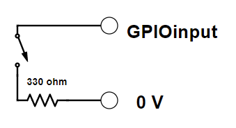
A GPIO pin left unconnected is in a floating state, and must be "forced" high (a positive voltage) or low (ground) so it has a definite resting value. This is done by connecting a resistor from the pin to either 3.3 V (pulling it high) or to ground (pulling it low) — either with a resistor wired into your own circuit (external), or using the pull resistor built into the SBC's GPIO controller and enabled in the FPP GPIO Inputs page (internal).
Note
Configure only one of the two — do not enable an internal pull resistor and wire an external one on the same pin.
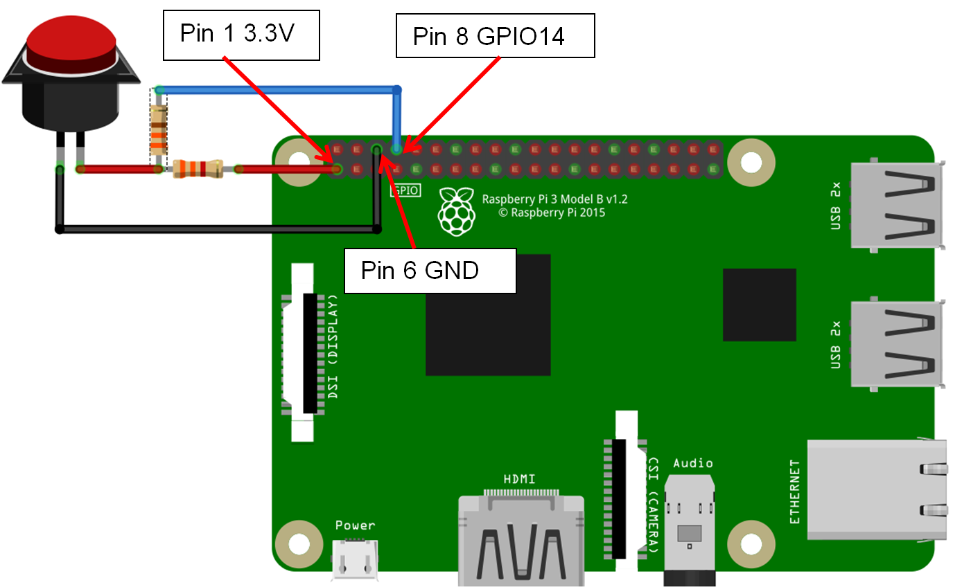
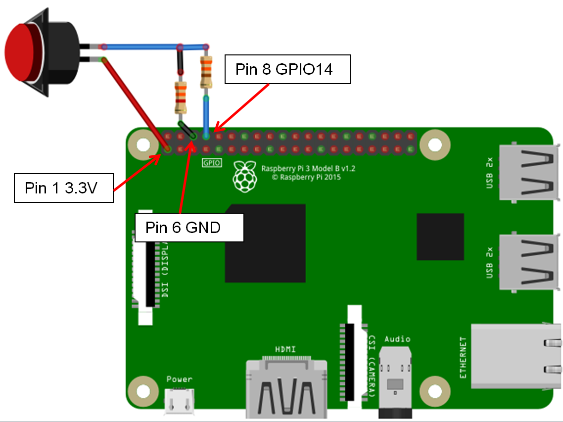
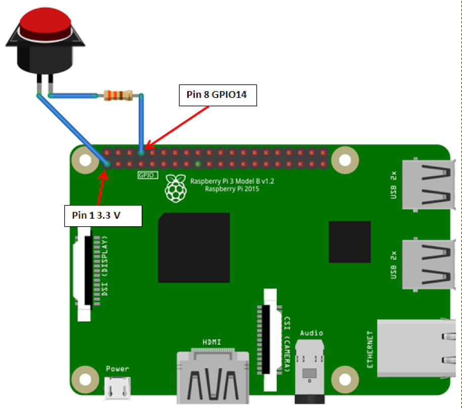
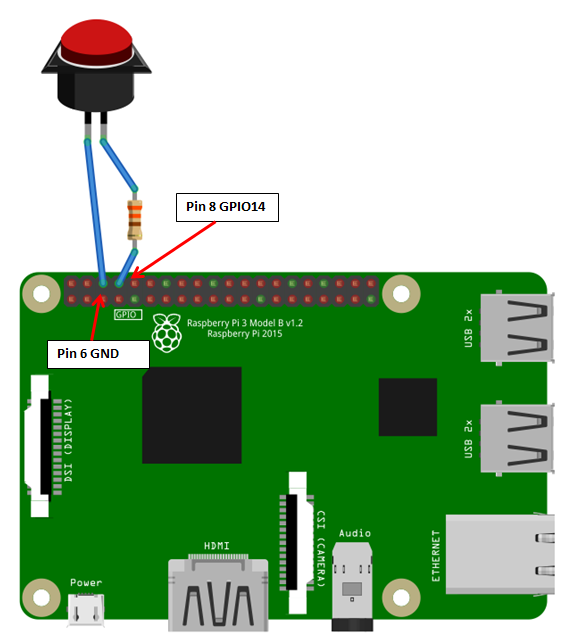
The examples below use GPIO14 on a Raspberry Pi 3. If you use the internal pull‑up/down resistor, you can drop the external 3.3 kΩ resistor and the connections it makes.
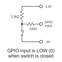
External resistor, pulled high
With the resistor wired to 3.3 V, the pin rests high; pressing the button pulls it to ground, producing a falling trigger.
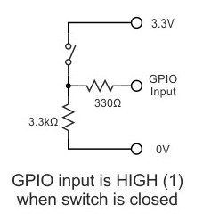
External resistor, pulled low
With the resistor wired to ground, the pin rests low; pressing the button connects it to 3.3 V, producing a rising trigger.
Internal resistor, pulled low
No external resistor is needed — enable the Pull Down option for this pin on the GPIO Inputs page instead. The pin rests low, and pressing the button (wired to 3.3 V) produces a rising trigger.
Internal resistor, pulled high
Enable the Pull Up option for this pin on the GPIO Inputs page. The pin rests high, and pressing the button (wired to ground) produces a falling trigger.
Switch types and trigger direction
There are two basic types of switches:
- Normally Open (NO) – lets electricity flow only while it is pressed.
- Normally Closed (NC) – lets electricity flow until it is pressed, then stops the flow.
And the GPIO trigger itself fires on one of two edges:
- Rising trigger – the voltage on the pin transitions from ground to a positive voltage (roughly 1.3 V or higher).
- Falling trigger – the voltage transitions from a positive voltage back towards ground.
Which edge corresponds to a press depends on the combination of: whether the pin is pulled high or low, whether the switch is Normally Open or Normally Closed, and whether you want the action to happen on press or release — you can configure commands for both edges if you want different actions for each (see GPIO Inputs → Trigger Commands).
For example, with the pin pulled high and a Normally Open button: pressing the button triggers a Falling event, and releasing it triggers a Rising event.