GPIO Inputs
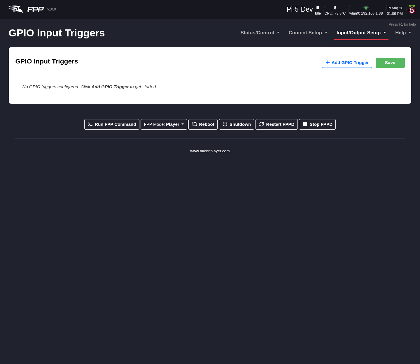
GPIO Inputs trigger internal FPP events from an external input — a button, a motion sensor, a switch. Each input connects to a pin on the FPP's GPIO header or to an add‑on I/O board such as the PiFace. Open Input/Output Setup → GPIO Inputs.
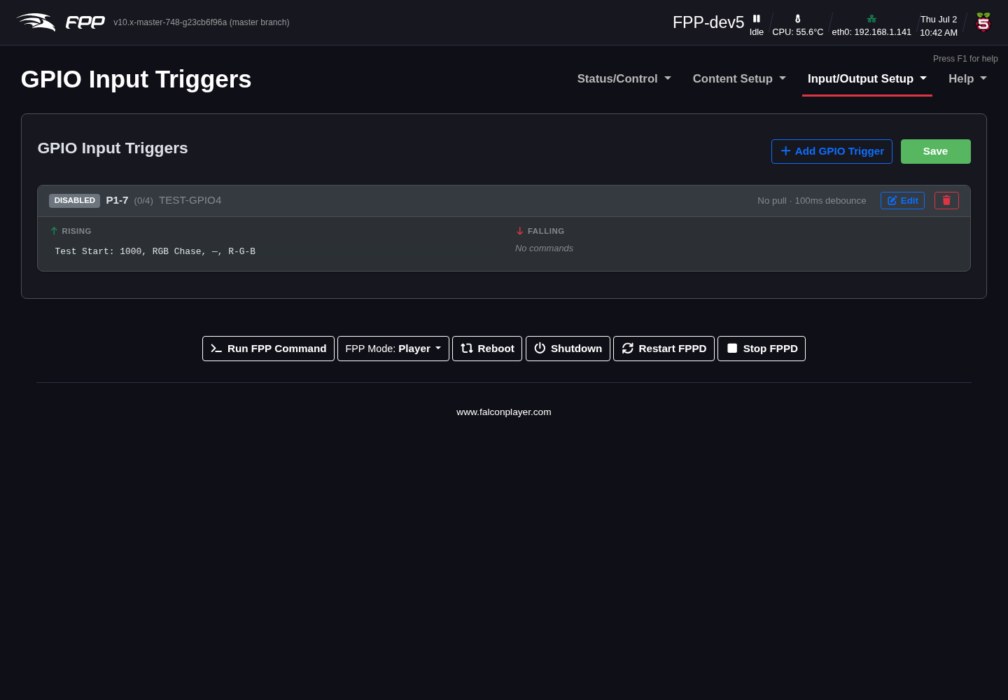
Each configured pin is shown as a card listing, at a glance, whether it is enabled, which pin it uses, its description, its pull and debounce settings, and the commands attached to its rising and falling edges. Use + Add GPIO Trigger to create one, Edit to change one, the bin icon to remove one, and Save to store your changes.
Note
As elsewhere in FPP, nothing takes effect until you click Save on the page itself — closing the edit dialog with Apply only updates the card.
Note
If you select None/External pull, make sure your circuit establishes a definite high or low state — a floating pin can cause false triggers. Pi GPIO pins are 3.3 V and are not 5 V tolerant.
The Configure GPIO Trigger dialog
Adding or editing a trigger opens a dialog where all of a pin's configuration lives. It is organised into three panels.
Pin & General Settings
- GPIO Pin – the pin this trigger uses. Pins already assigned to another trigger are not offered, so you cannot configure the same pin twice. On a Raspberry Pi's 40‑pin header each pin is labelled with its GPIO number (gpiochip/line), and a line under the selector describes the chosen pin — its GPIO number, whether it has an internal pull‑up/down, and, if the pin is reserved by your cape or a channel output, what is using it. (On other boards, and on I/O expanders, the chip/line numbers can change between boots, so they are not shown.) A trigger saved before a cape claimed its pin keeps that pin, marked reserved.
- Enabled – whether this trigger is active. Leave it unticked to keep a configuration without it firing.
- Description – what the input is for, e.g. Start button or Emergency stop. Up to 128 characters.
- Pull Up / Down – the resting state of the pin:
- None / External Pull – relies on a pull resistor in your own circuit.
- Pull Up – the pin reads HIGH at rest, so a button wired to ground produces a falling edge when pressed.
- Pull Down – the pin reads LOW at rest, so a button wired to 3.3 V produces a rising edge when pressed.
Trigger Commands
Each pin can run commands on up to three events. Every list uses the same Add Command button, which opens the FPP Command Editor (see Command Presets), and commands can be reordered or deleted once added.
- Rising Edge Commands – run when the input goes HIGH (typically the button being pressed, with a pull‑down).
- Falling Edge Commands – run when the input goes LOW (typically the button being released).
- Long‑Press / Hold Commands – optional. Set a Hold Time (ms) and the commands here fire once the input has been held for that long. 0 disables the hold behaviour; the maximum is 30000 ms.
Note
When a hold command fires for a press, the falling commands for that same press are suppressed — so a short press and a long press can do genuinely different things without the short‑press action also running.
Options
- Debounce – filters mechanical switch bounce.
- Debounce Time (ms) – signals within this window are ignored. The default is 100 ms; raise it for a particularly "dirty" switch (10–60000 ms).
- Debounce On – Both edges debounces press and release; Rising only debounces the press and lets the release fire immediately; Falling only does the reverse.
- Re‑enable GPIO After Trigger – optional suppression that stops a button
being re‑triggered too quickly. While suppressed, further presses are ignored.
- Always enabled (no suppression) – no delay; immediate re‑triggering is allowed.
- Re‑enable after a fixed delay – lock the input for a set Delay (ms) after each trigger (100 ms to 1 hour).
- Re‑enable when player becomes idle – keep the input locked until FPP finishes playback. If no playback starts within 2 seconds, the input re‑enables automatically, so a mis‑fire cannot lock the button out.
- Illuminated Button LED – optional; drives a GPIO output for a lit
button, so the button itself can show what the show is doing.
- LED Output Pin – which GPIO output the LED is wired to, or None.
- Idle LED Mode – what the LED does at rest: Off (dark), On (lit, showing the input is ready), or Pulsing at the Pulse half‑period (ms) you set (500 gives a 1 Hz blink). While the input is suppressed after a trigger, the LED is held off whatever this is set to.
- Trigger Mode – what the LED does when the button fires: None (idle mode only), Follow input (lit while held), Flash N times (150 ms on, 150 ms off, then back to idle), or Stay on for N ms then back to idle.
Click Apply to accept the dialog, then Save on the page.
Typical uses
- A button to start or stop a sequence or the show.
- A motion sensor to activate a special sequence.
- A switch to trigger another external device.
- A lit button whose LED pulses while idle and stays on while the show runs, using the Illuminated Button LED options above.
- A single button doing two jobs — a short press starts the show, a long press (via Hold Commands) shuts the device down.
Note
GPIO inputs require real board hardware and correct wiring. When in doubt about voltage levels, use an appropriate interface or opto‑isolator.