Channel Outputs
The Channel Outputs page configures how FPP outputs channel data to the controllers, hats and capes connected to it. Open Input/Output Setup → Channel Outputs. The available tabs depend on your SBC and any attached cape.
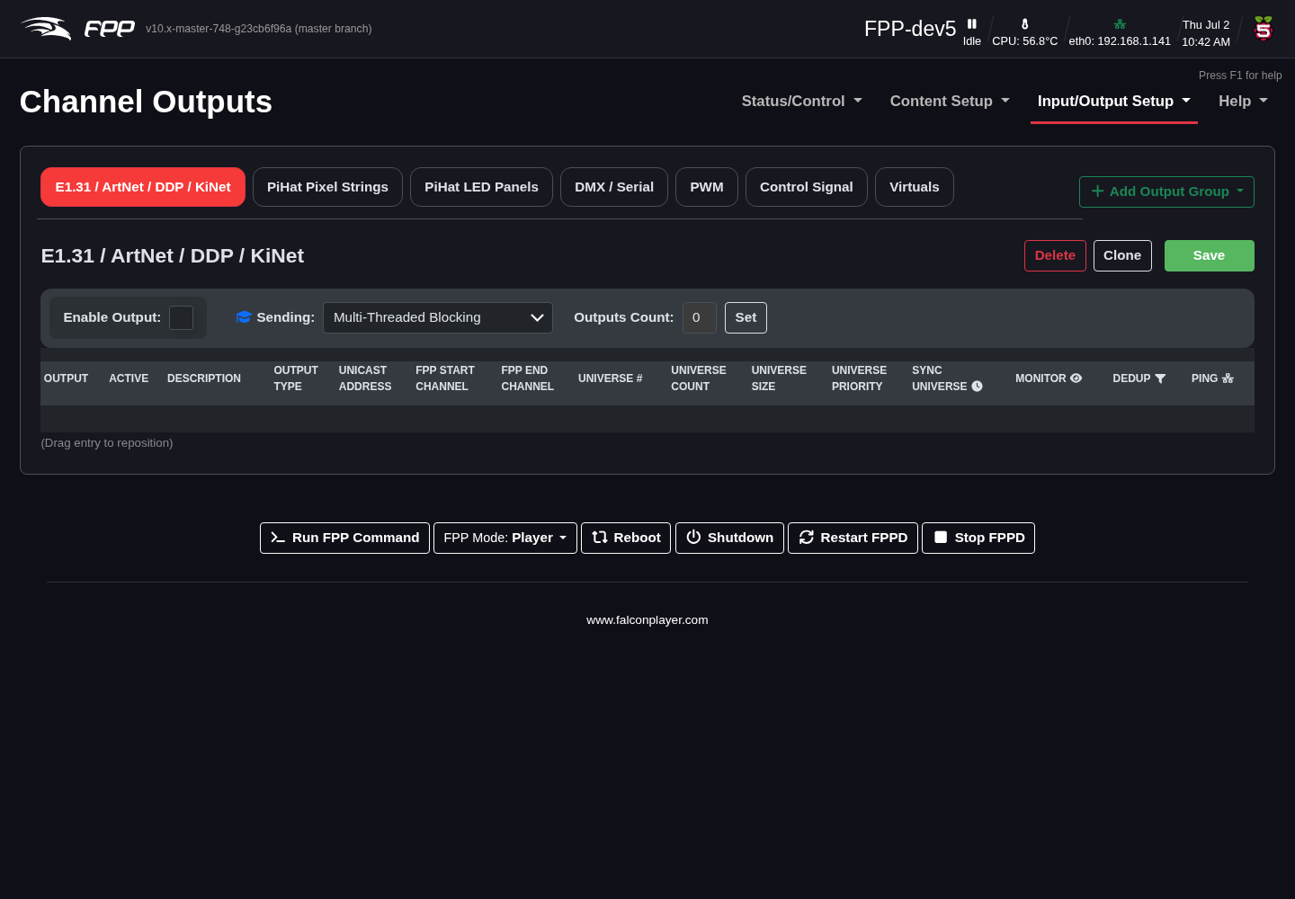
Set up your outputs to match the controller connected to FPP and the settings in your sequencing software. The output types are:
- E1.31 / ArtNet / DDP / KiNet – for controllers connected over Ethernet (or a switch). DDP is preferred where supported (e.g. Falcon and KulpLights controllers with recent firmware, ESP PixelStick). Output over Wi‑Fi is possible but not recommended.
- Pixel Strings (shown per cape, e.g. PiHat Pixel Strings, K8‑B) – WS281x pixels driven directly by a Pi hat or BeagleBone cape, or from the GPIO pins. FPP uses the attached cape's EEPROM to build the correct page; without a programmed EEPROM the section is blank and you must install a Virtual EEPROM (below). On a Raspberry Pi, FPP 10 drives these pins with DPI on every model.
- LED Panel Matrices – P10/P5 panels via a BeagleBone Octoscroller‑type cape, a Pi matrix hat, or a ColorLight card.
- PWM – PWM outputs (servos, single‑colour dimming) on a cape that provides them and has a signed EEPROM.
Every other output type — DMX / Serial, GPIO, Virtuals, SPI, PWM (via PCA9685) and Control Signal — is added on demand with the + Add Output Group button, described under Additional output groups at the end of this chapter.
Changed in v10
The Channel Outputs screen was redesigned. The old single Other tab, which held DMX, serial, control and virtual types together, has been removed. Those outputs are now organised into categories that you add as tabs with + Add Output Group, so the page shows only the output types you actually use.
E1.31 / ArtNet / DDP / KiNet
Note
You only need to enable/configure these outputs if this device sends pixel data to external devices over the network. It does not apply to locally attached hats/capes or serial DMX ports.
Your universes, FPP start channels and sizes must match your sequencer and controller. Using FPP Connect in xLights (the UDP option under Tools) to upload the configuration is the recommended method, as it avoids typing errors.
Warning
If you do not intend to send E1.31/ArtNet/DDP data but select the UDP option in FPP Connect, it will configure and activate these outputs, which can cause lag/stutter and unexpected results.
- Enable Output – enable network output.
- Sending – the send strategy (Advanced):
- Multi‑Threaded Blocking (default) – multiple threads; send a packet and wait for acknowledgement before the next. Uses FPP's multi‑threading for better performance.
- Single‑Threaded Blocking – one thread, wait for acknowledgement.
- Multi‑Threaded Non‑Blocking – multiple threads, send the next packet as soon as it is ready.
- Single‑Threaded Non‑Blocking – one thread, send as soon as ready.
- Pacing – the maximum rate data is sent to each unicast controller (Advanced). Pacing to what the controller's network port can absorb prevents switch buffer overruns and silently dropped packets. Most pixel controllers have 100 Mbps ports, so 90 Mbps (the default) is recommended; choose a higher rate for gigabit controllers. Multicast and broadcast are not paced, and Disabled sends at full line rate. A note beside it estimates the maximum frame rate your largest controller can be fed at that rate, and each output row has its own Pacing override.
- Outputs Count – the number of output rows, typically one per controller (even when a controller uses several universes). Click Set to create the rows.
- Set / Save / Clone / Delete – create the rows, save, copy a row to those below it, or delete a row.
For each output row:
- Active – transmit this line's universes (activate only the outputs you actually need).
- Description – identify the controller.
- Output Type – how the data is sent: DDP (recommended where supported), E1.31 Multicast, E1.31 Unicast (more efficient — prefer Unicast for E1.31), or ArtNet. DDP is normally Raw Channel numbers; DDP‑One Based makes each controller start at channel 1 (you must then configure those devices to match).
- Unicast Address – for Unicast or DDP, the target device's IP.
- FPP Start Channel – the absolute channel configured in your sequencer for this range.
- FPP End Channel – calculated, to help verify your entry.
- Universe #, Universe Count, Universe Size – the starting universe, how many universes on this line (multiple per line is recommended), and channels per universe (commonly 512 or 510 — keep it consistent across your show).
- Universe Priority – priority for the E1.31 packets when more than one source targets a device.
Note
If a paced controller needs more data per frame than its pacing rate can carry, its frames arrive late or cut short and its lights stutter. FPP now spots this and raises a warning naming the controller, the rate it needs and the rate it is paced at, with a button to this page. To fix it, raise that row's Pacing override if the controller has a gigabit port; otherwise lower the sequence frame rate, switch the controller to DDP, or move some pixels to another controller. Do not simply disable pacing — that turns the stutter into packets silently dropped by the switch.
Pixel Strings
The Pixel Strings tab (named for the detected cape) configures WS281x pixels wired to the hat/cape or GPIO. Common controls:
- Enable (Cape Type) – enable the pixel‑string output (untick to disable without losing the configuration).
- Cape Config – the cape type from the EEPROM (some, like the K16, offer expansion‑board and serial options).
- Testing – output test patterns (stays active until turned off): Port Number (white pixels at the start of each string indicate its port), Pixel Count by Port, Pixel Count by String, and Red/Green/Blue/White Fade.
- Pixel Timing – selects the timing group the ports run at. Changing it re‑offers each port's protocol list; a port set to a protocol the new group does not contain moves to that group's first protocol.
- Clone String – copy a string's settings to others, advancing the start channel.
Per port:
- Port – the hat's output port; click + to add a virtual string to a port (for different daisy‑chained models needing individual adjustment).
- Description – a label for the port.
- Start Channel – matches the start channel in your sequencer (highlighted orange if there may be an error — hover for details).
- Pixel Count – pixels on the port (red if it exceeds the port's capacity).
- Press F2 to auto set – fills the next row's start channel for contiguous ports.
- Group Count – group pixels that always display identically.
- End Channel – the ending channel (calculated).
- Direction – Reverse feeds data as if from the end of the string.
- Protocol – the pixel chipset the port drives. FPP 10 added per‑port protocols, so one cape can drive different pixel types on different ports. Besides the usual ws2811 / ws2801, the list covers the TM18xx family (tm1803, tm1804, tm1809, tm1812, tm1814, tm1814a), the UCS family (ucs1903, ucs1904, ucs1912, ucs2903, ucs2904, and the 16‑bit ucs7604, ucs8903, ucs8904), GS8206 / GS8208, and SK6812 / SK6812RGBW. The column is hidden on capes where every port offers only one protocol, so you will not see it on a ws281x‑only cape.
- Color Order – match your pixels' colour order.
- Start Nulls / End Nulls – number of null nodes used to boost transmission distance at each end.
- Zig Zag – for props like a mega‑tree where one string feeds several strands; enter how many times the string changes direction. Do not use this if you set Strands/String in your sequencer.
- Brightness – lower brightness can look better on dense props and reduces power draw.
- Gamma – correction for the non‑linear way we perceive brightness, and to match pixels from different vendors.
Configuring the Virtual EEPROM
From FPP 6 onward, the advanced pixel output protocols require an EEPROM. If your hat/cape has none, configure a Virtual EEPROM, choosing the type for your output. Examples:
- PiHat – two ports (two GPIO pins), driven via DPIPixels so on‑board audio keeps working; limited to 50 pixels per port without a licence.
- DPIPixels‑24 – up to 24 ports without disabling on‑board audio; 50 pixels per port without a licence.
- rPi‑28D / rPi‑MFC – Hanson Electronics boards.
- F16‑B / F32‑B / F4‑B / F8‑B / F8‑Bv2 / F8‑PB – Falcon/Kulp DIY boards.
Note
FPP 10 removed the old rpi_ws281x driver on Raspberry Pi and drives
those pins with DPIPixels instead. DPI uses the same GPIO pins, works on
every supported Pi model, and does not conflict with the on‑board audio — so the
variants that used to disable on‑board audio are gone, and RPIWS281X capes are
no longer offered in the UI.
Existing configurations migrate themselves, with no action needed from you:
FPP remaps the output type when the config loads, rewrites
co-pixelStrings.json on disk at boot, and writes the migrated version back out
the next time you save the page. A third‑party cape with a physically burned
RPIWS281X EEPROM is used as‑is (the pin format is the same); any pin DPI cannot
drive is skipped with a warning rather than failing the whole cape. The
rPi‑28D is a special case — its third output is ws2801 over SPI, which DPI
cannot drive, so it maps to the 4‑output variant and that protocol is rewritten
to ws2811.
- RGB‑123 / PB‑16 / PocketScroller / Spixel – various boards (Spixel drives 16 strings of APA102/LPD6803/LPD8806 directly from the Pi GPIO).
Some types offer additional board‑specific options — get the correct EEPROM and board type from your vendor. If a Virtual EEPROM needs a licence for its advanced features, a blue banner explains this; the Cape Info link opens the Cape Info page with more detail and a link to obtain the licence (see Pixel Port Licensing).
Screenshots pending — cape hardware required
Full captures of the Pixel Strings tab need the relevant cape fitted so the ports are shown; these will be added from a cape‑enabled system.
LED Panel Matrices
Configures LED panels (P10/P5 are most common), driven by a ColorLight card or a connected hat/cape. One FPP device can control multiple drivers; the practical limit depends on matrix size and the SBC's single‑core speed, so test for performance.
Note
For any output beyond a hat/cape you need a dedicated Ethernet port for each ColorLight receiver.
Click Add Panel Matrix and choose Hat/Cape or ColorLight. There are three settings screens — BeagleBone Hat/Cape, ColorLight, and Pi Hat/Cape. Common settings:
Note
FPP 10 allows several panel matrices to share one cape, so a cape‑driven setup is no longer limited to a single matrix the way it was in earlier releases. Multiple ColorLight panels were already supported.
Each matrix you add gets its own sub‑tab — Panel Matrix 1, Panel Matrix 2 and so on — so every matrix keeps its own layout, start channel and settings. Work through them one tab at a time; the settings below apply per matrix.
- Enable LED Panels – enable panel output.
- Interface – for ColorLight, the dedicated Ethernet port for that receiver.
- Matrix Name – names each matrix (shown on its Panel Tab).
- Panel Layout (WxH) – number of panels wide × high.
- Single Panel Size (WxH) – pixel size and scan rate of each panel (P10 = 32×16, P5 = 64×32).
- Model Start Corner – typically Top Left for xLights, Bottom Left for Vixen (match your sequencer).
- Panel Gamma / Brightness – gamma correction and overall brightness.
- Panel Interleave – for panels using non‑standard data transmission.
- Color Depth – number of colours; reduce to minimise flicker on large sets (Hat/Cape only; ColorLight uses LEDVision for this).
- Panel Row Address Type / LED Panel Type – for panels with different row addressing or specialty panels (Pi Hat/Cape only).
- Start Channel / Channel Count – the panel array's absolute start channel and total channels.
- PWM Register Profile – shown for panels whose driver chips need a register
profile uploaded (FM6373, ICND1065L, SM16380SH). Either load a
.profilescapture catalog and pick a profile from the list (profiles captured at this panel's scan rate are listed first, labelled with the row driver and pitch they came from), or paste a single profile your supplier sent. Only the chosen profile is saved, in the output configuration, so it travels with a backup. FPP also lets the FM6373 family's output‑enable timing and register upload be tuned for panels that need it. (Cape hardware only.) - Row addressing – BeagleBone capes now support panels that use ABC shift register row addressing.
Screenshots pending — cape hardware required
Additional output groups (Add Output Group)
The tabs above (E1.31/ArtNet/DDP/KiNet, the cape's Pixel Strings, PWM and LED Panels) appear automatically based on your hardware. Every other output type lives in an output group that you add yourself: click + Add Output Group at the right of the tab strip and pick a category. That category then becomes a new tab, where you add and configure individual outputs.
The categories, and the output types in each, are:
| Category (tab) | Output types |
|---|---|
| DMX / Serial | DMX-Open, DMX-Pro, Generic Serial, uDMX, Pixelnet-Lynx, Pixelnet-Open, Renard, LOR, LOR Enhanced, Generic UDP |
| GPIO | GPIO, GPIO-595, PCF8574, MCP23017 |
| Virtuals | HTTP Virtual Display, HTTP Virtual Display 3D, Virtual Display, Virtual Matrix |
| SPI | Generic SPI, SPI-nRF24L01, SPI ws2801, MAX7219 Matrix |
| PWM | PCA9685 |
| Control Signal | MQTT Output, Control Channel, USB Relay |
A category disappears from the + Add Output Group menu once you have added it, and the menu reads All groups already added when every category is on screen.
What each category is for:
- DMX / Serial – DMX, Pixelnet, Renard and LOR over a USB/serial adapter.
Select the serial device and protocol and map the channel range to it. USB serial
adapters are numbered in the order they are found, so
ttyUSB0can be a different adapter after a reboot; pick the adapter's by‑id name (or, for an adapter without a USB serial number, its by‑path name, which follows the USB socket) so the output stays on the right port. On a PocketBeagle 2 cape whose DMX/Renard line driver sits on a pin with no UART transmit, FPP sends from the PRU instead, so those outputs work unchanged. LOR Enhanced now defaults to 1 Mbps and keeps its channel count in step with the number of units; the speed choices are labelled with roughly how many all‑changing pixels each can carry at 40 fps (e.g. 800 at 1 Mbps). Because FPP now sends only the pixels that changed, paced to the line rate, real sequences usually fit far more. Generic UDP sends raw channel data to an arbitrary UDP destination. - GPIO – drive GPIO pins, or an I/O expander (PCF8574, MCP23017) or shift register (GPIO-595), from channel data — typically for relays.
- Virtuals – on-screen outputs rather than physical ones. Enabling HTTP Virtual Display 3D here activates the browser-based 3D preview, and HTTP Virtual Display the 2D one — see the 3D Virtual Display chapter. Virtual Matrix renders channel data to a framebuffer/display.
- SPI – devices on the SPI bus, including ws2801 pixels and MAX7219 matrices.
- PWM – PCA9685 PWM controllers, for servos and single-colour dimming. (A cape with its own PWM hardware gets a dedicated PWM tab instead, provided the cape's EEPROM is signed.)
- Control Signal – outputs that signal rather than light: publish channel values over MQTT, drive a USB Relay, or use a Control Channel to trigger FPP behaviour from channel data.
After any change, click Save and, when prompted, Restart FPPD.
Note
Adding an output group only creates the tab. You still add individual outputs inside it, and each output needs its own start channel and channel count.