The PipeWire Audio & Video Pipeline
FPP 10 replaces the simple audio/video handling of the 9.x series with a flexible pipeline built on PipeWire (the audio/video graph), WirePlumber (which links the graph together) and GStreamer (which decodes media and handles network streaming). This lets FPP route one audio or video source to multiple simultaneous outputs, each with its own volume, delay, equalisation and format — and to send and receive audio and video over the network.
Everything in this chapter is reached from the buttons on FPP Settings → Audio/Video (with Media Backend set to PipeWire (Advanced)). Each page runs live against the PipeWire graph; most have Save and Save & Apply buttons (Apply regenerates the pipeline and re‑links it).
Key concepts. An output group is a "combine sink" that fans one signal out to several destinations. An input group / mix bus collects one or more sources and routes them to output groups. The routing matrix connects inputs to outputs. These apply to both audio and video.
Sound Card Aliases
Audio/Video → Configure Sound Card Aliases.
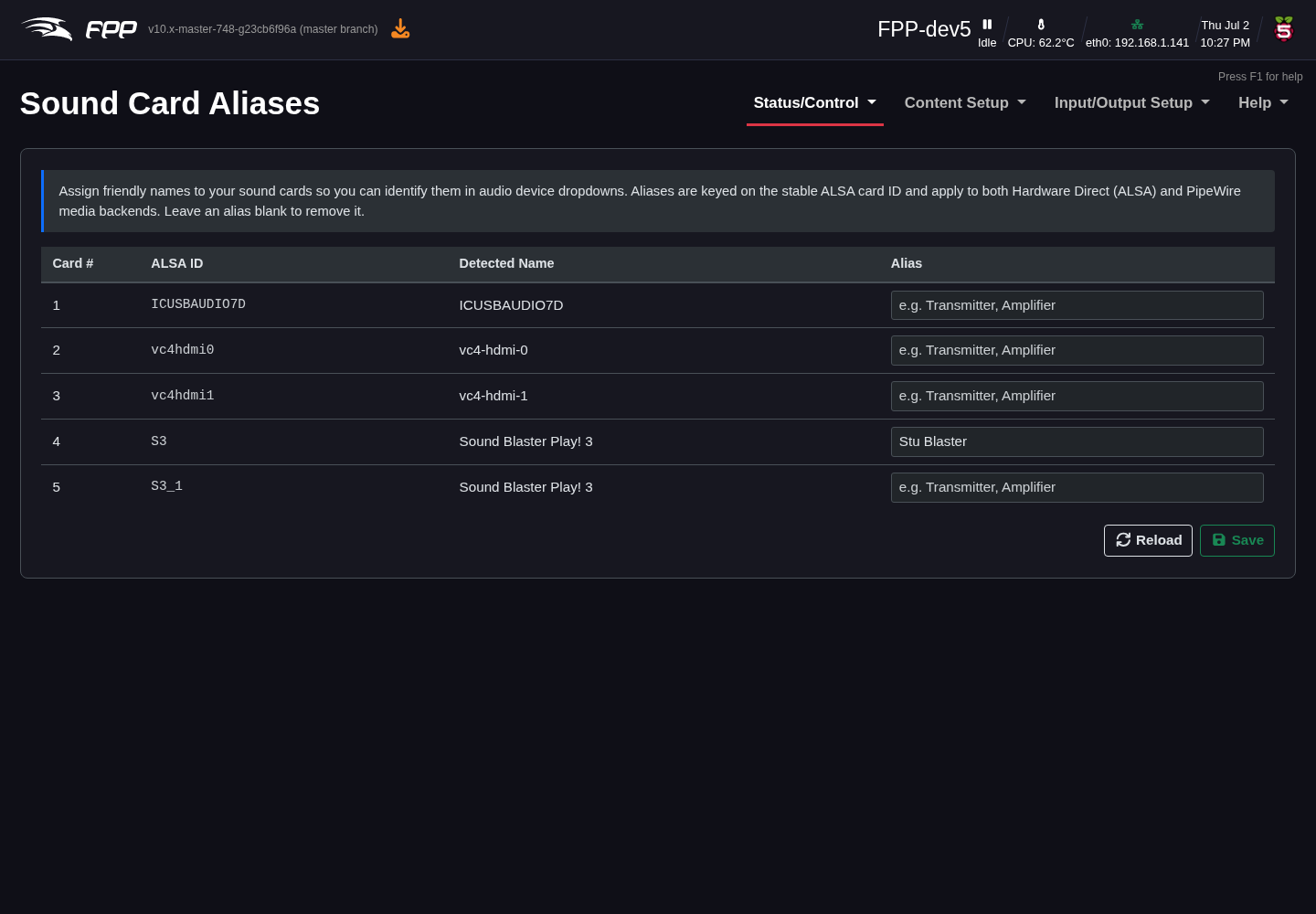
Audio devices have long, cryptic system names (for example
usb-Creative_Technology_Ltd_Sound_Blaster_Play__3...). This page lets you give
each card a short, friendly alias (e.g. "Stu Blaster") that is then used
throughout the audio pages, making groups much easier to configure.
Audio Output Groups
Audio/Video → Configure Output Audio Groups.
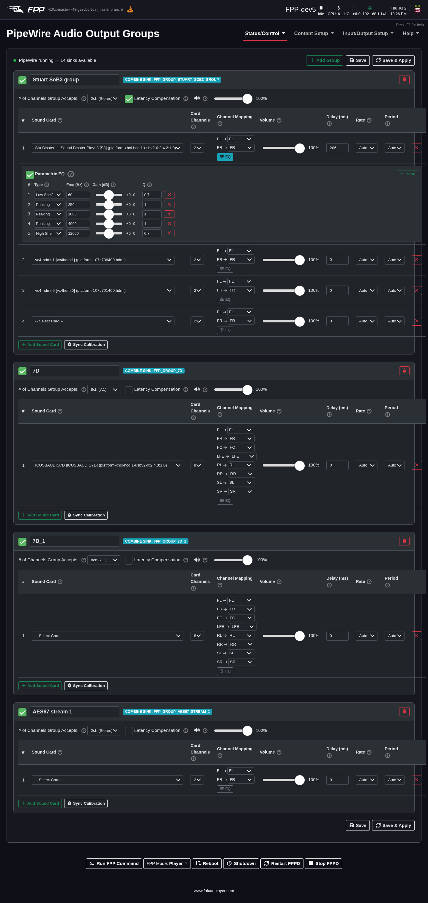
An audio output group is a virtual sink that plays the same audio through several sound cards at once. Click Add Group, name it, and add the sound cards that belong to it. For the group you set:
- # of Channels Group Accepts – e.g. 2ch (Stereo) or 8ch (7.1).
- Latency Compensation – align outputs that have different latencies.
- A group volume.
For each sound card in the group:
- Sound Card – chosen by its alias.
- Card Channels – how many channels the card provides.
- Channel Mapping – map each group channel to a card channel (e.g.
FL → FL,FR → FR,LFE → LFE), so you can send, say, only the left channel to one card. - Volume, Delay (ms) – per‑card level and delay (delay is very useful to time‑align distant speakers or compensate for network/receiver latency).
- Rate / Period – sample‑rate and buffer period (usually Auto).
- Parametric EQ – enable per‑card EQ and + Band to add bands, each with a Type (Low Shelf, Peaking, High Shelf), Frequency (Hz), Gain (dB) and Q.
Add Sound Card adds another member; Sync Calibration helps measure and set the per‑card delays.
Input Mixing (Mix Buses)
Audio/Video → Configure Input Mixing.
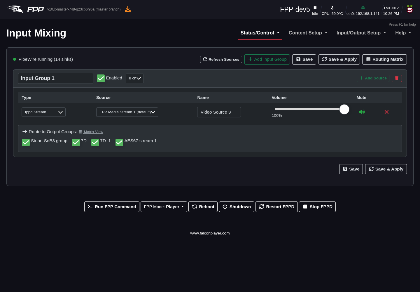
An input group (mix bus) gathers one or more audio sources and routes them to output groups. For each input group you set its name, whether it is Enabled, and its channel count, then add sources. Each source has a Type (e.g. fppd Stream), a Source (e.g. FPP Media Stream 1), a Name, a Volume and a Mute control. Tick the Route to Output Groups boxes to send the mixed result to the chosen output groups (or open the Routing Matrix for a grid view).
Routing Matrix
Audio/Video → Open Routing Matrix.
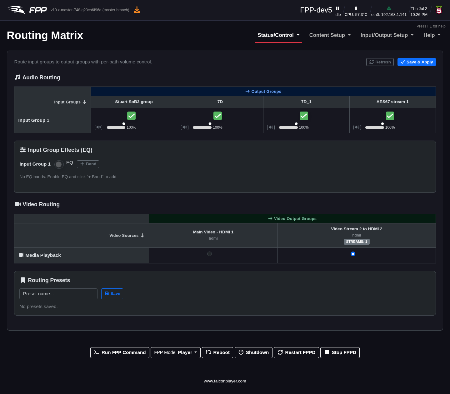
The Routing Matrix is the single place to connect everything:
- Audio Routing – a grid of Input Groups (rows) against Output Groups (columns). Tick a cell to route that input to that output, with a per‑path volume slider for each connection.
- Input Group Effects (EQ) – enable EQ on an input group and add bands.
- Video Routing – a grid of Video Sources against Video Output Groups; select which source feeds each video group.
- Routing Presets – save a complete routing configuration (audio and video assignments) by name and reload it later.
Click Save & Apply to activate the routing.
Audio Mixer
Status page → the Mixer (sliders) button next to the volume control.
In PipeWire (Advanced) mode the Status page's volume slider is a single global master, but the graph has many independent levels. The Audio Mixer dialog shows them all at once, as faders with live signal meters:
- Master volume – the global master; it multiplies with every level below.
- Media Stream Slots – the level of each FPP media stream.
- Output Groups – each group's level and, beneath it, its member sound cards. Output strips show the effective level after the master and group levels are applied.
- Input Groups – the members of each input group (mix bus).
- Routing Matrix – the level of each input → output path.
Each strip has a Mute button and, where possible, a Listen (speaker) button that plays that point in the graph in your browser — useful for checking a feed without walking out to the speakers. Sections can be collapsed, and the dialog remembers which are open. Changes save as you make them, exactly as if you had made them on the corresponding settings page.
Pipeline Graph
Audio/Video → Visualise Current Pipeline.
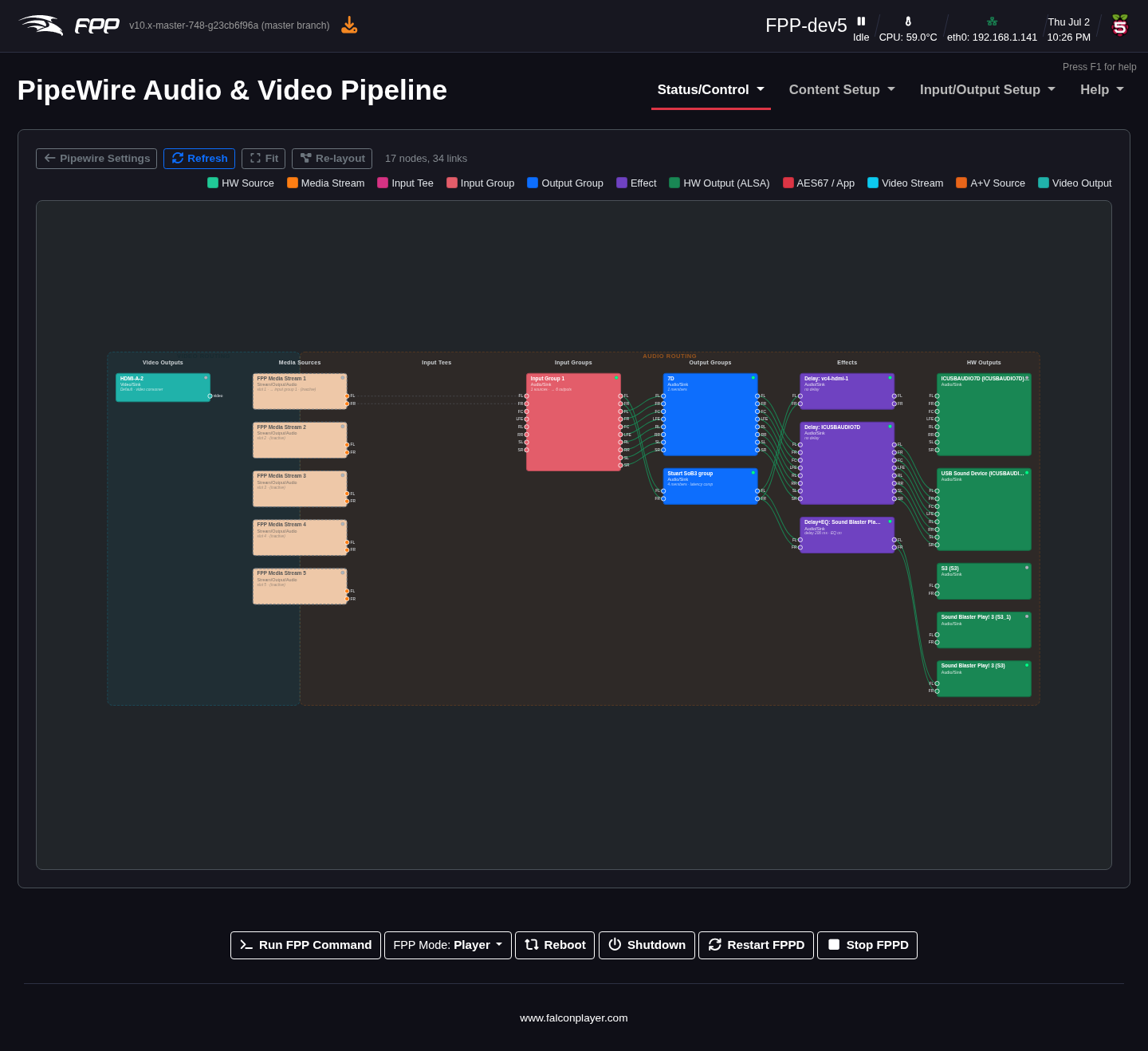
This page draws the live PipeWire graph — the media streams, combine sinks, filter chains (delay/EQ), sound cards and video nodes, and the links between them. Producers and consumers are colour‑coded. It is a valuable troubleshooting view for confirming that audio and video are flowing where you expect.
AES67 Audio‑over‑IP
Audio/Video → Configure AES67 Instances.
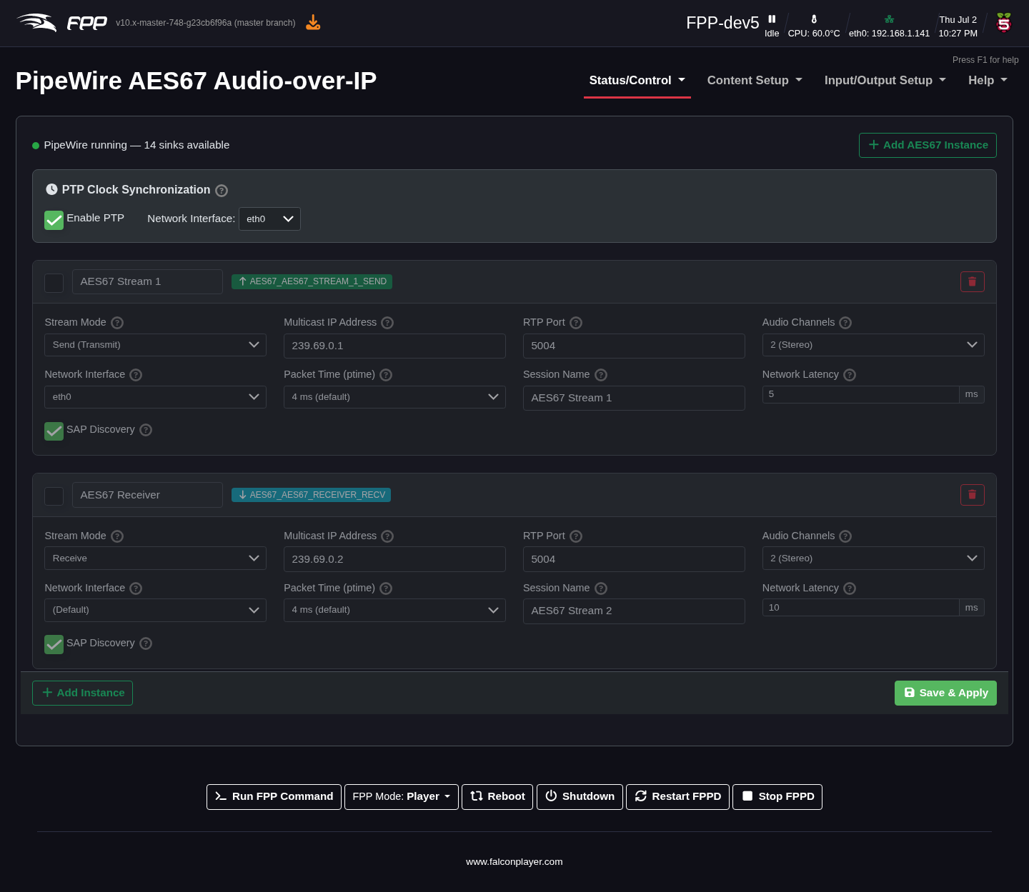
AES67 streams uncompressed, PTP‑synchronised audio over the network as multicast RTP — the professional standard used by many consoles, DSPs and powered speakers. Each AES67 instance you define appears in the PipeWire graph as a virtual sink (Send) or a virtual source (Receive), so you can add it to an audio output group and per‑card delay and EQ apply to it too. FPP announces streams via SAP and derives RTP timestamps from a PTP clock, so compliant receivers discover and lock to them automatically.
Click Add AES67 Instance to create one, and Save & Apply to rebuild the pipeline. The page requires Media Backend to be set to PipeWire (Advanced); otherwise it shows a notice instead of the settings.
Stream status
The status line at the top of the page reports PipeWire's state, how many of the configured streams are actually running, the PTP clock state, and how many AES67 streams have been discovered on the network. It refreshes every ten seconds, so it is worth watching for the first minute after FPPD starts — PTP moves from listening to master or follower as the clock election settles.
PTP clock synchronisation
PTP (IEEE 1588 Precision Time Protocol) provides sample‑accurate clock synchronisation between AES67 devices. These settings apply to the whole device, not to a single instance:
- Enable PTP – run the PTP clock. Enable it when you need tight sync between several FPP instances or with professional AES67 gear.
- Network Interface – which interface the PTP clock runs on; it is also the source address for streams that do not name an interface of their own. Only wired interfaces are listed — PTP needs deterministic latency (and, where the network card supports it, hardware timestamping), so Wi‑Fi cannot hold sync.
- Domain – the PTP domain number, 0–127. Every device that must share a clock has to be on the same domain. AES67 gear normally uses domain 0, so leave this alone unless your console or DSP is set otherwise.
- Clock Role – who provides the clock (unrelated to FPP's Player/Remote
mode):
- Auto – the default. FPP joins the election at a low priority: it becomes the clock when it is the only device on the domain, but yields to a console or DSP that wants the role.
- Master – FPP tries to win the election. Use this only if FPP is meant to be the master clock for the network.
- Slave – FPP follows another clock and never becomes the master.
Once PTP is running the status line shows either PTP master (this device), or PTP synced to the grandmaster's clock ID together with the current offset (shown in ns, µs or ms as it settles). If it has not locked yet you get PTP not synced plus the port state, which is normal for the first few seconds. Beside the PTP controls a small panel shows the live PTP State, the Grandmaster (with its address, and whether it is reached via a boundary clock), the Domain, the Offset and the Stream Source Rate. Send streams wait for PTP to lock before they start transmitting, and their status says so while they wait.
Tip
If FPP keeps announcing itself as the clock when you have a proper master on the network, check that both are on the same Domain and set FPP's Clock Role to Slave.
Note
FPP marks its own traffic for QoS automatically — RTP audio as AF41 (DSCP 34) and PTP messages as EF (DSCP 46), the codepoints AES67 recommends. There is nothing to configure. If the installed PTP software is too old to accept DSCP settings, FPP retries without them and notes it in the log.
Per‑instance settings
Each instance has a checkbox to enable it, an editable name, a badge showing the PipeWire node it creates, an SDP button and a delete button. SDP shows the stream's session description, with Copy and Download .sdp buttons, for tools that need it handed to them as text — Stream Monitor, VLC and the like. (AES67 equipment discovers FPP's streams through SAP and does not need it.) If a stream's settings do not add up — for example tuning options that contradict each other — the instance shows a warning explaining what to change. Its settings are:
- Stream Mode – Send (Transmit), Receive, or Both (Send & Receive). Send creates a virtual sink; Receive creates a virtual source.
- Multicast IP Address – the multicast group, from the AES67
239.69.x.xrange. Give each instance its own address to avoid conflicts. - RTP Port – the UDP port for RTP traffic; the AES67 default is 5004. Use different ports if several instances share one multicast address.
- Audio Channels – channels in this stream, up to 8 (most setups use 2). The output group feeding a Send stream must be set to the same channel count.
- Network Interface – the wired interface used for the multicast traffic; (Default) uses the PTP interface set above.
- Packet Time (ptime) – the packetisation interval: 1 ms (the default — mandatory for every AES67 device, the only packet time Dante transmits, and it gives tighter timing) or 4 ms (optional, less CPU, stereo only — wider streams would not fit in one packet). It must match at both ends.
- Session Name – the name other devices see in the SAP announcement.
- Network Latency – the target buffer for receive streams, in milliseconds (AES67's minimum is 1 ms; 1–20 ms is typical). Lower means less delay but more risk of dropouts on a busy network.
- SAP Discovery – announce sent streams, and auto‑create receive streams from announcements heard on the network.
Opus RTP Audio Streaming
Audio/Video → Configure Opus RTP Instances.
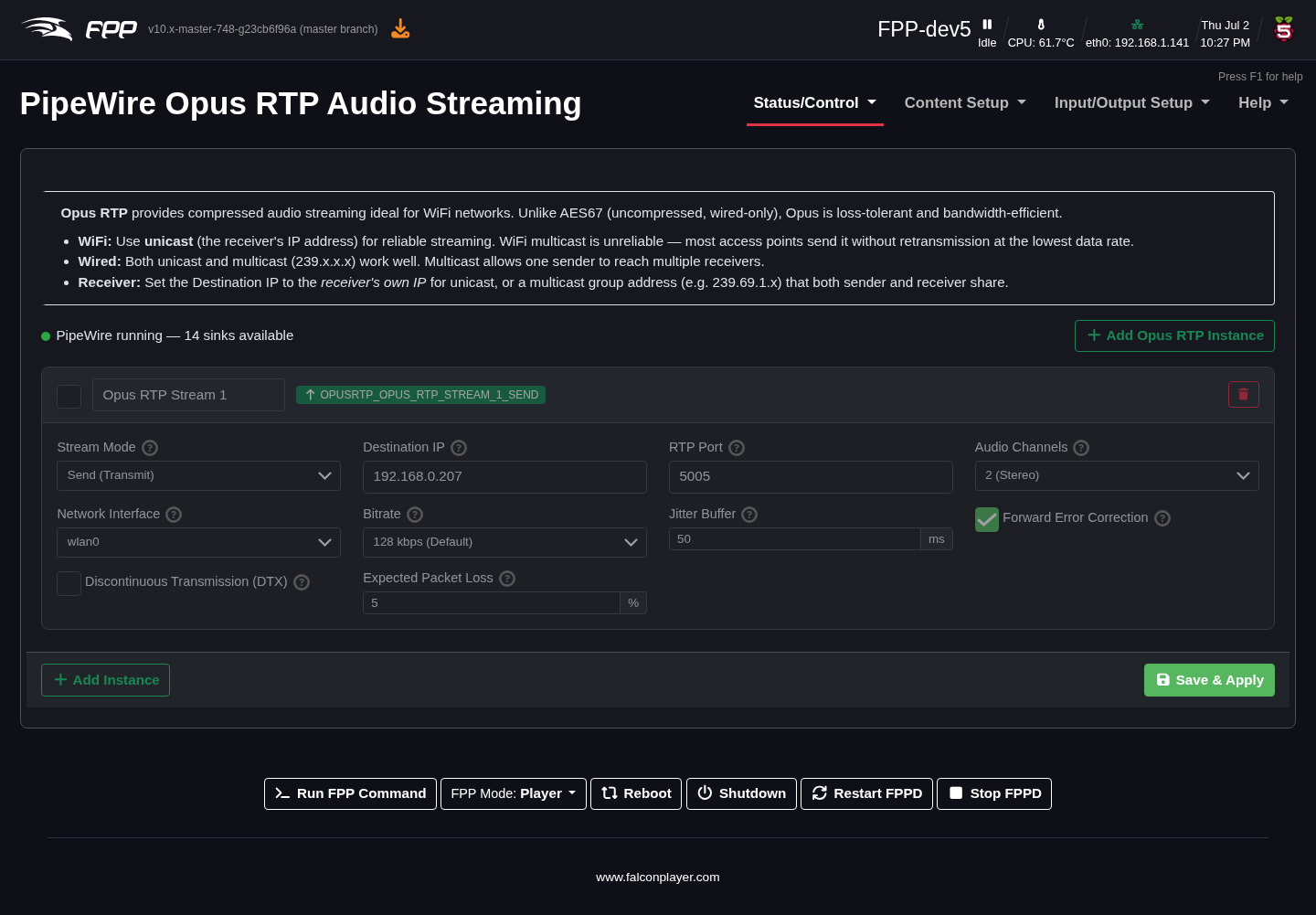
Opus RTP streams compressed (Opus‑encoded) audio over the network — far lower bandwidth than AES67 and tolerant of packet loss, which makes it the right choice for WiFi links and for remote players or listeners. Like AES67, each instance appears in the PipeWire graph and can be used in the audio routing.
Use unicast (the receiver's own IP address) over WiFi: most access points send
multicast at the lowest data rate with no retransmission. On wired networks both
unicast and multicast (239.x.x.x) work well, and multicast lets one sender feed
several receivers.
The status line next to the PipeWire indicator shows how many of the configured streams are running, along with the error text for any pipeline that failed to start; it refreshes every ten seconds. Previously the page reported only PipeWire's own state, so a stream that never started looked the same as a healthy one.
Each instance has:
- Stream Mode – Send (Transmit), Receive or Both.
- Destination IP – the receiver's IP for unicast, or a shared multicast group address for wired multicast.
- RTP Port – the UDP port; the default is 5005.
- Audio Channels – Opus handles mono and stereo natively; higher counts use multiple Opus streams.
- Network Interface – the interface to send or receive on (e.g.
wlan0with unicast,eth0for either). - Bitrate – 32 kbps to 320 kbps; 128 kbps is the default and is ample for stereo music, while 64–96 kbps copes where bandwidth is tight.
- Jitter Buffer – receive‑side buffering in milliseconds: around 50 ms for wired unicast, 100–150 ms for WiFi unicast, more again if you must use WiFi multicast. Higher values add delay but ride out network timing variations.
- Forward Error Correction – Opus in‑band FEC, which adds redundancy so lost packets can be reconstructed. Recommended on WiFi.
- Discontinuous Transmission (DTX) – send fewer packets during silence to save bandwidth, at the cost of slight artefacts when audio resumes.
- Expected Packet Loss – tunes the FEC encoder for the loss rate you expect; 5% is typical for WiFi, 0–1% for wired.
Note
Opus RTP audio is marked AF41 (DSCP 34) automatically, so switches and access points that honour QoS give it priority over bulk traffic.
VBAN Audio Streaming
Audio/Video → Configure VBAN Streams.
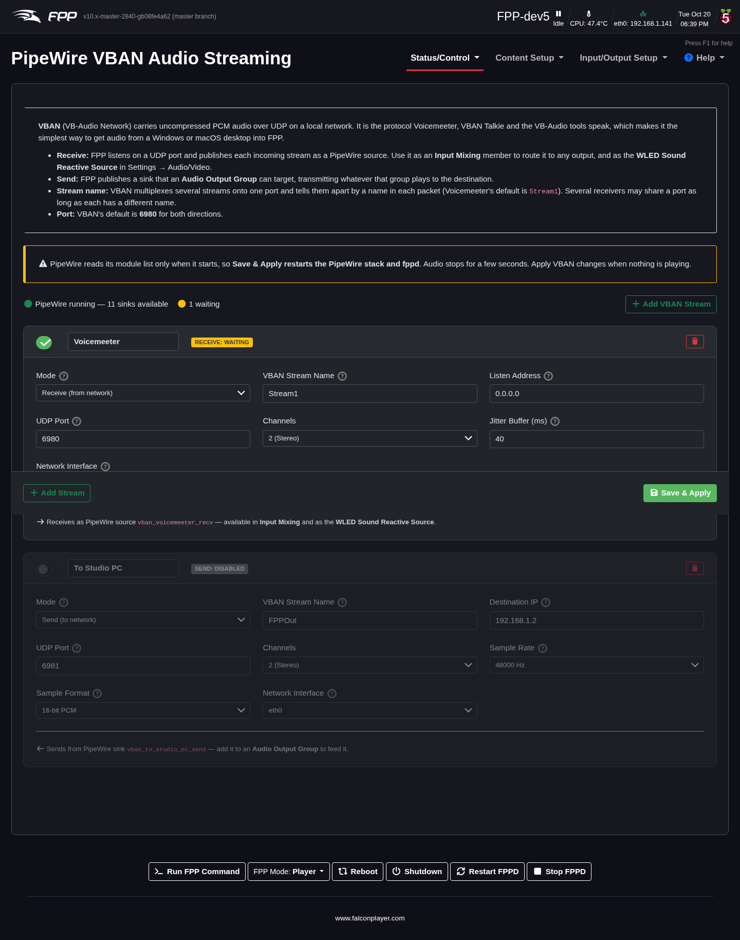
VBAN (VB‑Audio Network) carries uncompressed audio over UDP on your local network. It is the protocol spoken by Voicemeeter, VBAN Talkie and the other VB‑Audio tools, which makes it the simplest way to get audio from a Windows or macOS desktop into FPP — or to send FPP's audio back the other way. Each stream becomes a node in the PipeWire graph:
- a receive stream is an audio source — add it as a member on the Input Mixing page to route it to any output group, or pick it as the WLED Sound Reactive Source on FPP Settings → Audio/Video;
- a send stream is an audio sink — add it to an Audio Output Group and whatever that group plays is transmitted. Nothing is sent until a group feeds it.
Each stream has:
- Enable and Name – the name also sets the PipeWire node name, so renaming a stream already used in a group means re‑selecting it there.
- Mode – Receive, Send, or Both on the same port.
- VBAN Stream Name – the name carried inside every packet (up to 16
characters, case sensitive); Voicemeeter's default is
Stream1, and it must match at both ends. A receiver may leave it blank to accept whatever arrives. - Listen Address (receive) – normally
0.0.0.0, to accept from any sender. - Destination IP (send) – the machine running the VBAN receiver.
- UDP Port – VBAN's default is 6980. Several receivers can share a port if their stream names differ.
- Channels, and for send streams Sample Rate (usually 48000 Hz) and Sample Format (16‑bit PCM is the most widely supported) – these must match the far end.
- Jitter Buffer (receive) – how much network timing variation to absorb; 100 ms suits most links.
- Network Interface – leave on (Default) unless the stream must use a specific connection.
A status badge on each stream reads Live (the node is in the graph), Waiting (applied, but nothing received yet — normal for a receiver until a matching packet arrives), Not applied or Disabled.
Note
Save & Apply restarts PipeWire and FPPD, so audio stops for a few seconds — apply VBAN changes when nothing is playing. VBAN needs the PipeWire (Advanced) media backend.
Tip
Short dropouts at regular intervals, each about as long as the jitter buffer, are caused by packets being reordered on the network, not by FPP. Lowering the jitter buffer (try 60 ms) makes each dropout much shorter; a wired connection on the sending machine usually removes the cause.
Video Output Groups
Audio/Video → Configure Video Output Groups.
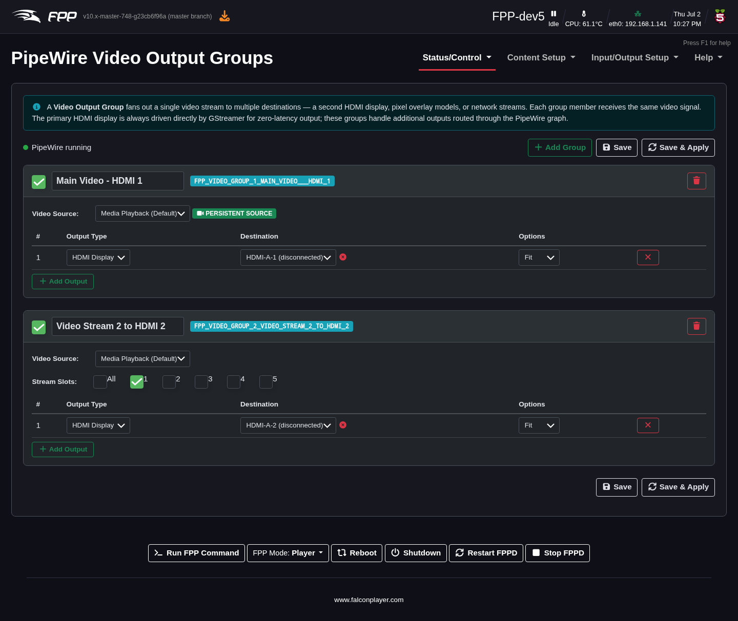
A video output group fans a single video stream out to several destinations at once. (The primary HDMI display is always driven directly by GStreamer for zero‑latency output; these groups handle additional outputs routed through the PipeWire graph.) For each group set a name, the Video Source (Media Playback, or a persistent input source), optionally which Stream Slots (1–5) it uses, then add outputs. Each output has:
- Output Type – HDMI Display, a Pixel Overlay model, a Network (RTP) stream, or a Network (RTSP) stream (see RTSP Video Outputs below).
- Destination – the specific HDMI connector, overlay model, network address,
or for RTSP the stream's path (e.g.
/live). - Scaling (HDMI) – how the video is fitted to the display:
- Fit – the whole frame fits on the display at its original aspect ratio; black bars fill any leftover space.
- Fill – the video covers the whole display at its original aspect ratio; the overhanging edges are cropped.
- Stretch – the video is stretched to the exact display size, distorting it if the shapes differ.
- Region (HDMI) – which portion of the source frame this display shows, as percentages. Giving two displays opposite halves splits one video across both from a single decode.
- Network options – for RTP/RTSP members, the width, height, frame rate, encoding and bitrate, and whether to carry Audio in the same stream. An RTP member offers a Download SDP button for VLC/ffplay.
This is how you drive a second HDMI screen, mirror video onto an LED matrix (via an overlay model), and stream video over the network — all from one playing video. FPP keeps video pixels square, so a picture is never squashed by a mismatch between the source and output shapes.
RTSP Video Outputs
Audio/Video → Configure RTSP Outputs.
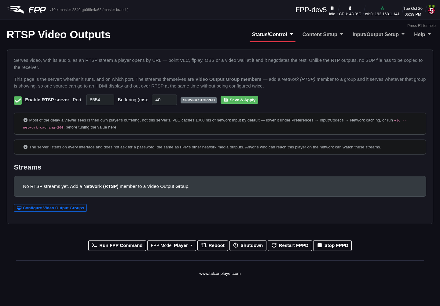
FPP can serve video, with its audio, as an RTSP stream that a player opens by URL — point VLC, ffplay, OBS or a video wall at it and it negotiates the rest. Unlike the RTP outputs, no SDP file has to be copied to the receiver.
This page controls the server itself: Enable RTSP server, its Port (default 8554) and Buffering (ms) inside each stream (default 40; lower means less delay, but a jittery source may drop frames), then Save & Apply. The streams are members of Video Output Groups: add a Network (RTSP) member to a group and it serves whatever that group shows, so one source can go to an HDMI display and out over RTSP at the same time. The page lists the streams currently being served, with their URLs.
Tip
Most of the delay a viewer sees is their own player's buffering. VLC
buffers 1000 ms of network input by default — lower it under Preferences →
Input/Codecs → Network caching (or run vlc --network-caching=200) before
tuning the buffering here.
Note
The RTSP server listens on every interface without a password, like FPP's other network media outputs: anyone who can reach the player on the network can watch the streams.
Video Input Sources
Audio/Video → Configure Video Input Sources.
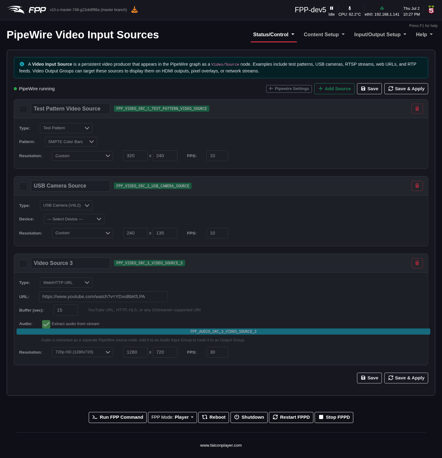
Video input sources are persistent video producers that video output groups can route from (they survive consumers connecting and disconnecting). Supported types include:
- Test Pattern (
videotestsrc) – e.g. SMPTE bars, a moving ball or a solid colour at a chosen size/frame rate. - USB Camera (
v4l2src) – a connected camera or capture card (/dev/video0, …). FPP lists the modes the device actually supports (resolution, frame rate and format — raw, Motion JPEG and so on) to choose from, and offers camera controls: Anti‑flicker (50 Hz or 60 Hz mains — rolling bands or pulsing brightness under artificial light nearly always mean this is set for the wrong region) and Exposure (camera default, auto, or a manual Shutter time). - RTSP Network Stream (
rtspsrc) – a stream from an IP camera, optionally with Extract audio from stream to make its sound available as a PipeWire audio source.
Each source shows a live preview once it is enabled and applied, so you can check framing and exposure on the page itself. Define a source here, then select it as the Video Source of a video output group to send a live camera or test pattern to HDMI, an overlay model, or the network.
A note on remote synchronisation
When FPP runs as a remote, the GStreamer pipeline continuously fine‑adjusts its playback rate to converge on the player's position, keeping audio and video frame‑accurate over long shows. This is automatic; the remoteIgnoreSync setting disables it if ever needed. See the MultiSync chapter for the player/remote setup.
Note
This chapter covers the configuration UI. The full technical
architecture (services, WirePlumber linking, GStreamer pipelines, diagnostics)
is documented in the FPP repository under docs/FPP_Audio_Architecture.md,
docs/PipeWire_Video_Routing.md and docs/GStreamer_PipeWire_Clock_and_Sync.md.