GPIO Inputs
GPIO Inputs trigger internal FPP events from an external input — a button, a motion sensor, a switch. Each input connects to a pin on the FPP's GPIO header or to an add‑on I/O board such as the PiFace. Open Input/Output Setup → GPIO Inputs.
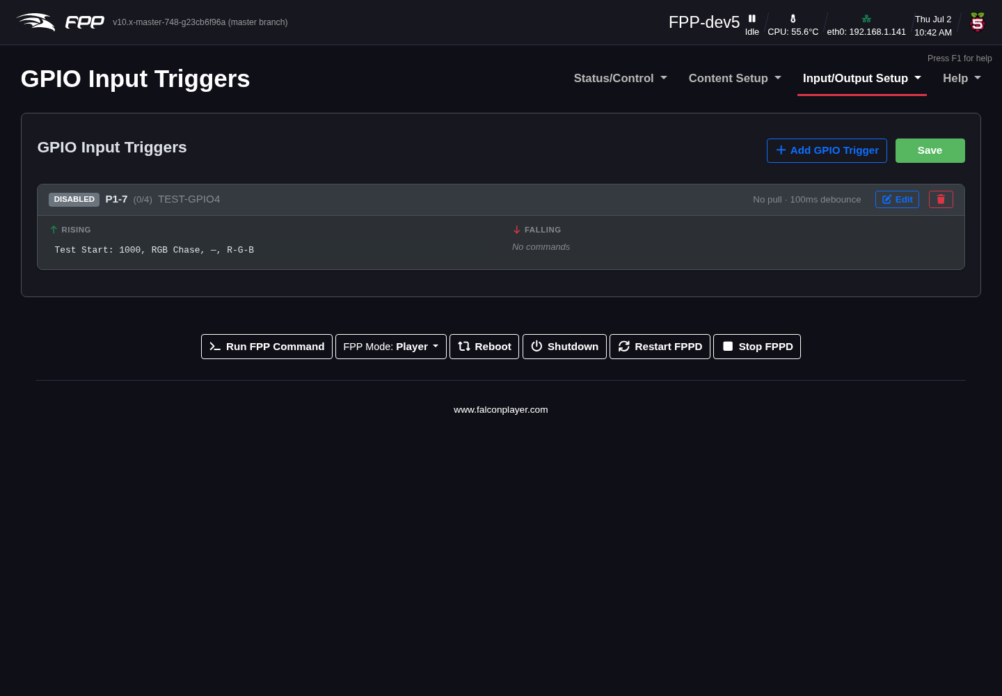
Each pin can trigger two events: one on the rising edge and one on the falling edge. You can set the resting state to high (pull up) or low (pull down) using the internal resistors, or use external resistors.
Note
If you select None/External, make sure your circuit establishes a definite high or low state — a floating pin can cause false triggers. Pi GPIO pins are 3.3 V and are not 5 V tolerant.
Settings
For each pin:
- En – enable the pin for GPIO input.
- Hdr‑Pin – the header pin location (for reference).
- GPIO# – the GPIO number.
- GPIOD – the Linux pin label used by the manufacturer (for reference).
- Pull up/Down – set the internal pull‑up or pull‑down resistor.
- Debounce (ms) – signals within this window are ignored to filter switch bounce; increase it for a particularly "dirty" switch.
- Description – note what this input is used for.
- Commands – choose the FPP Command to run on the rising and/or falling event (see Command Presets).
Typical uses
- A button to start or stop a sequence or the show.
- A motion sensor to activate a special sequence.
- A switch to trigger another external device.
Note
GPIO inputs require real board hardware and correct wiring. When in doubt about voltage levels, use an appropriate interface or opto‑isolator.